It satisfies the AC withstand voltage test of 35kV/300mm2 cable with capacitance less than 0.1945uF, test frequency 30-300Hz, test voltage 52kV and test time 60 minutes.
It satisfies the AC withstand voltage test of 10 kV/300 mm2 cable with capacitance less than 0.9387uF, test frequency 30-300 Hz, test voltage 22 kV and test time 5 min.
For service of product purchase and technical maintenance, please call 4008828058
The device is mainly aimed at AC withstand voltage test of cross-linked cables, hydroelectric generators, main transformers, buses, GIS, etc. It has a wide range of application. It is an ideal withstand voltage equipment for local, municipal and county high voltage test departments and electric power installation and repair engineering units.
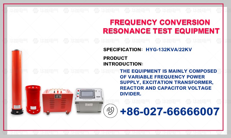
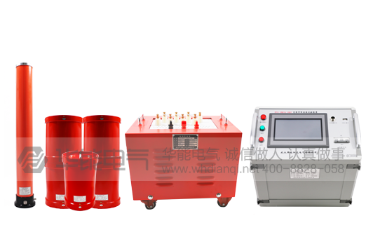
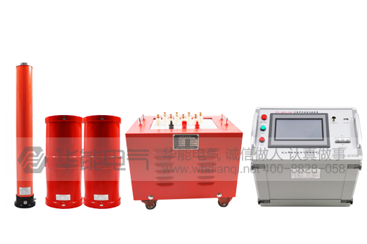
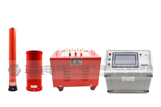
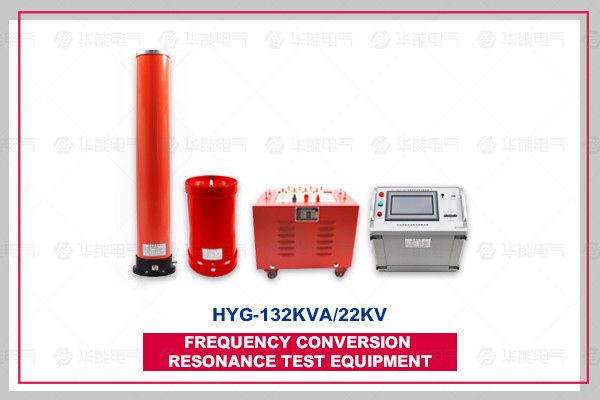
The device is mainly composed of frequency conversion control power supply, excitation transformer, reactor, capacitor voltage divider and compensation capacitor.
Main technical parameters
1. Rated capacity: 132 kVA
2. Rated voltage: 22kV
3. Rated current: 6A
4. Measurement Accuracy: System RMS Level 1.5
5. Working frequency: 30-300 Hz
6. Output waveform of device: sine wave
7. Quality factors: Q of the device itself is greater than 30 (f = 45Hz)
8. Waveform Distortion Rate: Output Voltage Waveform Distortion Rate <1%
9. Input power supply: single-phase 220 or three-phase 380V voltage, frequency 50 Hz
10. Working hours: 60 minutes under rated load; 1.1 times overvoltage for 1 minute
11. Temperature Rise: Temperature Rise < 65K after 60 min continuous operation under rated load
12. Protection Functions: Overvoltage, Overcurrent, Zero Start-up, System Detonation (Flash) and other Protection Functions
13. Environmental Temperature: -20-55 C
14. Relative humidity: <90% RH
15. Altitude: <3000 M
2. Determination of Device Capacity
The capacity of the device is set at 132KA, which is divided into three sections of reactor. The single section of reactor is 44KA/22KV/2A/40H.
Verification:
The AC withstand voltage test of 1.35kV/300mm2 cable with capacitance less than 0.1945uF, test frequency 30-300 Hz, test voltage 52 kV, test time 60 min.
Using three-section reactor in series, L=40*3*1.15=138H
Test frequency:
F=1/2 pi_LC=1/(2*3.14*138*0.1945*10-6)=30.72 Hz
Test current:
I = 2 pi fCU test = 2 pi x 30.72 x 0.1945 x 10-6 x 52 x 103 = 1.95A
AC withstand voltage test of 2.5 km for 2.10 kV/300 mm2 cable, capacitance less than 0.9387uF, test frequency 30-300 Hz, test voltage 22 kV, test time 5 min.
Using three-section reactor in parallel, L=40/3=13.33H
Test frequency:
F=1/2 pi_LC=1/(2*3.14*13.33*0.9387*10-6)=44.99 Hz
Test current:
I=2pi fCU test=2pi*44.99*0.9387*10-6*22*103=5.84A
It meets the experimental requirements.
3. Equipment combination mode in test
Combination mode
Subjects
reactor
(44KA/22KV three sections)
Excitation transformer
Output Selection
Test Voltage (KV)
10 kV/300 mm2 cable 2.5 km
Three Sections Parallel Connection Using Reactors
1kV
Less than 22kV
35kV/300mm2 cable 1km
Three-section Series Connection Using Reactor
3kV
Less than 52kg
IV. System Configuration and Its Parameters
(1) Frequency conversion power supply HYG-6kW 1
1) Rated output capacity: 6kW
2) Working power supply: 220/380+10% V (single/three phase), power frequency
3) Output Voltage: 0-400V
4) Rated input current: 15A
5) Rated output current: 15A
6) Voltage resolution: 0.01 kV
7) Voltage measurement accuracy: 1.5%
8) Frequency regulation range: 30-300 Hz
9) Frequency Adjustment Resolution: <0.1Hz
10) Frequency stability: 0.1%
11) Running time: 60 minutes at rated capacity
12) Maximum temperature of components running continuously for 60 minutes at rated capacity <65K
13) Noise level: <50dB
14) Weight: about 10 kg
(2) HyGJL-6KA/1/3KV/0.4KV 1 excitation transformer
1) Rated capacity: 6kVA
2) Input voltage: 0-400V
3) Output Voltage: 1/3 kV
4) Structure: Dry
5) Weight: about 45 kg
(3) 3 sections of high voltage reactor HYGDK-44KA/22KV
1) Rated capacity: 44KA
2) rated voltage: 22kV
3) Rated current: 2A
4) Inductance: 40H/single section
5) Quality factor: Q > 30 (f = 45Hz)
6) Structure: Dry
7) Weight: about 42 kg
(4) One set of capacitive divider HYGFY-2500pF/60kV
1) rated voltage: 60kV
2) High Voltage Capacitance: 2500pF
3) dielectric loss: tg_ < 0.5%
4) Partial pressure ratio: 1000:1
5) Measurement accuracy: RMS 1.5
6) Weight: about 6 kg
Note: product appearance is subject to actual product, technical parameters and models are subject to change without prior notice. For more information on the list of products of huaneng products. National service hotline 4008828058
HYG series frequency conversion series resonant withstand voltage test device, which uses the way of adjusting the power supply frequency, makes the reactor and the capacitor to achieve resonance, so as to obtain high voltage and high current on the tested products. Because of its small power supply and small equipment weight, it has been widely praised and applied at home and abroad. It is a new method and trend of high voltage test at present.
The main functions and technical characteristics of our FM resonant device are as follows:
1. The device has the protection functions of over-voltage, over-current, zero-position start, system detuning (flashover). The protection value of over-voltage and over-current can be set according to user's needs. The flashover protection action of the test product can be recorded when flashing, so as to provide test analysis.
2. The whole device is light in weight and easy to use on site.
3. The device has three working modes: full-automatic mode, manual mode and automatic tuning manual boost mode. It is convenient for users to choose flexibly according to the site conditions and improve the test speed.
4. It can store and print data in different places. The number of data stored is digital, which is convenient for users to identify and search.
5. The starting point of frequency can be set arbitrarily in the prescribed range when the device scans frequency automatically. The direction of frequency scanning can be selected up and down. At the same time, the scanning curve can be displayed on the large LCD screen, so that users can intuitively know whether to find the resonance point.
6. Using the technology of DSP platform, the functions and upgrades can be added or subtracted according to users'needs, and the man-machine interface is more humanized.
7. The required power supply capacity is greatly reduced. Series resonant power supply generates high voltage and large current by resonant reactor and capacitor resonance. In the whole system, the power supply only needs to provide the part of active power consumption in the system, so the power required for the test is only 1/Q of the test capacity.
8. The weight and volume of the equipment are greatly reduced. In series resonance device, heavy high-power voltage regulator and common high-power test transformer are omitted. Moreover, the resonant excitation power supply only needs 1/Q of the test capacity, which greatly reduces the weight and volume of the system, generally 1/10-1/30 of the ordinary test device.
9. Improving the output voltage waveform effectively. Resonant power supply is a resonant filter circuit, which can improve the waveform distortion of output voltage and obtain good sinusoidal waveform. It can effectively prevent the wrong breakdown of the sample by harmonic peak.
10. Prevent large short circuit current from burning fault points. In the series resonance state, when the insulation weakness of the test sample is broken down, the circuit immediately detuning and the loop current rapidly drops to 1/Q of the normal test current. When the voltage withstand test is done with parallel resonance or test transformer, the breakdown current immediately rises by tens of times. Compared with the two, the short circuit current is hundreds of times different from the breakdown current. Series resonance can effectively find the insulation weakness, but there is no big short-circuit current burn fault point.
11. No recovery overvoltage will occur. When the sample breaks down, because of the loss of resonance condition, the high voltage will disappear immediately, the arc will be extinguished immediately, and the process of rebuilding the recovery voltage is very long. It is easy to disconnect the power supply before reaching the flashover voltage again. This process of voltage recovery is an intermittent oscillation process of energy accumulation, which is long and no recovery overvoltage will occur.