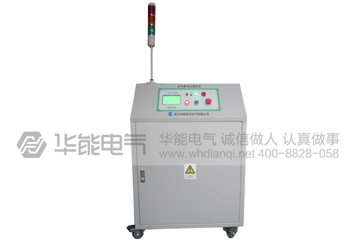
The voltage withstanding tester is suitable for standard insulating breakdown voltage withstanding test of insulating materials, bushing, power fittings and electronic products.
Implement ANSI D149 and GBT_1408.1-2006 standards.
Our company can customize any parameters of non-standard pressure products and equipment!
For service of product purchase and technical maintenance, please call 4008828058
HYG-50KV breakdown and withstand voltage tester integrated measurement and control system is a high voltage equipment automation information platform which integrates measurement and control. It consists of ultra-high speed, large capacity transient signal acquisition module, programmable amplifier, lower computer and executing mechanism as the core components. Through industrial control computer, it can realize full automatic control and fast signal analysis and processing of the whole system. Because the general industrial control computer is used as the information platform, it provides a broad space for the upgrade and expansion of the breakdown voltage tester in the future, and also provides the hardware basis for the construction of the laboratory information center. All the above parts are designed and manufactured according to the industrial process standards, which guarantees the safety, reliability, stability, accuracy and operation speed of the system.
HYG-50KV breakdown and withstand voltage tester is designed for the operating environment of high voltage laboratory, especially considering the characteristics of impact test. The technical performance index meets the requirements of implementing the 12.2.1 and 12.2.2 standards of ANSI D149.
The operation software is simple, intuitive and easy to operate in the interface.
General conditions of use
Elevation: 1000M
Ambient temperature: - 5 +40.
Relative humidity: 90%
Maximum Daily Temperature Difference: 25 C
Use environment: indoor
Non-conductive dust
No fire and explosion hazards
Existence of gases that do not contain corrosive metals and insulation
The waveform of power supply voltage is actual sine wave, and the waveform distortion rate is less than 5%.
Rating parameter value
1. Nominal Voltage Gear: 0-50kV, 2500V;
2. Rated voltage: 50kV, 30kV;
3. Capacity: 3kVA;
4. Boost rate: 2KV/s, 1KV/s, 0.5KV/s, 0.2KV/s and 0.1KV/s.
5. Current setting range: 0~20mA;
6. Test time: 5 minutes.
Note: product appearance is subject to actual product, technical parameters and models are subject to change without prior notice. For more information on the list of products of huaneng products. National service hotline 4008828058I. Main Characteristics
Full integration of measurement and control; high integration;
High Precision and High Speed Data Sampling
Industrial integration design has high stability, high reliability and excellent electromagnetic compatibility, without any additional shielding device.
Hardware and electrical interlocking to ensure the safety and reliability of operation;
II. Main Functions of Control Systems
The output voltage is automatically converted and displayed on the screen.
Overvoltage and overcurrent protection, automatic grounding;
Automatic boost: According to the set parameters, including setting voltage and setting time, a boost, hold and reset process is automatically completed.
It can intuitively display each withstand voltage situation, including breakdown voltage value, withstand voltage time, leakage current;
Emergency switching is different from manual switching. Emergency switching directly cuts off the main circuit power through buttons for abnormal conditions, such as power outage in control room.
Implementation of ANSI D149 and GBT_1408.1-2006
The following is ANSI D149 standard
12. steps
Note 2 - Note: Read Part 7 before any tests.
12.1 Method of applying voltage
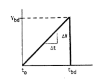
12.1.1 Method A, Short Time Test - Under the condition of a ratio given in Figure 1, add the same voltage to the test electrode from 0 until breakdown occurs. This short-time test method is used when no other method is specified.
12.1.1.1 When establishing a rate, in order to be included in a new rule, a rate should be selected so that for a series of samples, the average time of breakdown occurs is between 10 and 20 seconds. One or two groups of tests may be required to determine the most appropriate rate of increase. For most materials, 500V/s is usually used.
12.1.1.2 If the description file specifies a given rate of rise for this test, the given value must always be used regardless of whether or not the average breakdown time occasionally occurs outside the range of 10 to 20 seconds. If such incidents occur, they need to be recorded in the report.
12.1.1.3 In a series of tests of different materials, the same voltage rise rate is preferred and the breakdown time of these materials is between 10 seconds and 20 seconds. If the breakdown time does not meet the above range, it needs to be recorded in the report.
Voltage rise rate (V/S) +20%
One hundred
Two hundred
Five hundred
One thousand
Two thousand
Five thousand
Vbd is the breakdown voltage and TBD is the breakdown time.
Fig. 1 Voltage curve measured in a short time
12.1.2 Method B, step-by-step testing - applying a pre-start voltage on the test electrode and gradually increasing each test voltage for a period of time, as shown in Figure 2, until breakdown occurs.
12.1.2.1 Choose the initial voltage in the list in Figure 2, which is the closest to 50% of the experimental breakdown voltage measured in a short time or the expected breakdown voltage.
12.1.2.2 If the selected initial voltage is different from the value listed in Figure 2, it is suggested that the voltage rise at each stage should be 10% lower than the selected initial voltage.
12.1.2.3 The initial voltage is applied in this way, starting from 0 and rising to the required value at the fastest rate, without exceeding the allowable peak voltage in 6.1.3. The same requirement is applied to each stage of the voltage rise process. After the initial stage, the time taken to rise to the next stage should be counted as part of the next stage.
12.1.2.4 If the breakdown occurs in the process of the voltage rise to the next stage, the sample is described as having met the dielectric withstand voltage, and Vws is equal to the voltage of the completed stage. If the breakdown occurs before the end of any stage of voltage stability, the dielectric withstand voltage of this sample is defined as the voltage of the previous stage. Breakdown voltage is used to calculate withstand voltage strength. Medium compressive strength is calculated by material thickness and medium pressure. (See Figure 2)
12.1.2.5 Expected breakdown occurs in stages 4 to 10, but not less than 120 seconds. If more than one sample in the group does not satisfy this condition, the breakdown occurs in phase 3 or earlier, or less than 120 seconds. Whichever is larger, the test needs to re-select a lower initial voltage for testing. If the breakdown does not occur before stage 12 or is greater than 720 seconds, the initial voltage should be increased.
12.1.2.6 records the initial voltage, the voltage at each stage, the breakdown voltage, and the duration of the breakdown voltage. If the breakdown occurs when the voltage rises to the initial voltage, the breakdown time should be recorded as 0.
12.1.2.7 The duration of the voltage at each stage may be specified, depending on the purpose of the test. Twenty seconds and 300 seconds (5 minutes) are commonly used. For research purposes, it is also possible to have more than one time interval for a given material.
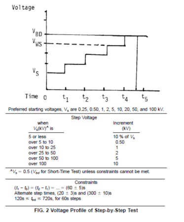
Vbd is breakdown voltage, Vws is dielectric withstand voltage
Preferred starting voltage for pre-start voltage
Step voltage stage voltage
Increment incremental constraints constraints (conditions)
Unless constraints cannot be met unless constraints cannot be met
Optional Stage Duration for Alternate Step Times
Figure 2 Step-by-step testing
12.1.3 Method C, Low Voltage Rise Rate Test Method - Apply voltage on the electrode at the rate shown in Figure 3 until breakdown occurs.
12.1.3.1 Selects the initial voltage according to the short time test method specified in 12.1.1. The initial voltage shall meet the specified requirements in 12.1.2.3.
12.1.3.2 Use this rate of voltage rise to raise the voltage from the initial value, which is specified in the relevant documents given by the test method. Usually this rate is selected.